A gasket factory does not become fully automated simply by replacing manual winding with a faster winding machine. A true production line must coordinate material feeding, winding, part transfer, dimensional verification, guide ring supply, assembly, unloading and production control as one connected process. If any of these stages still depends on slow manual transfer or an unstable upstream supply, the line may generate work-in-process rather than finished gaskets.
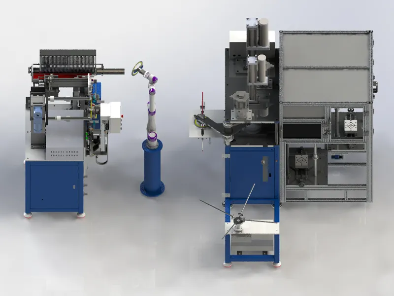
The SZMATE MSWG-25 is designed around this integrated production concept. Instead of treating winding and guide ring assembly as separate departments, the line connects an automatic winder, a six-axis collaborative robot, an automatic press and a guide ring feeding system. The winding element is produced, transferred, measured, accepted or rejected, assembled with a guide ring and moved to a collection station without repeated manual handling between the principal operations.
This guide explains how the line works, what its published specifications mean, how to estimate practical capacity and which manufacturers are most likely to benefit from this automation level. It also identifies the production data buyers should prepare before requesting a quotation from SZMATE. The purpose is not to present one machine as suitable for every factory. It is to help gasket manufacturers determine whether an integrated line matches their product mix, batch pattern, quality requirements and investment plan.
A fully automatic gasket manufacturing line is a coordinated production system that converts prepared metal and filler materials into assembled finished gaskets with limited manual transfer between the main operations.
The phrase “fully automatic” should describe the production route, not only the control panel. A machine may use PLC control and servo motors but still require an operator to move every winding element to a separate inspection table, load each guide ring and remove each finished gasket. That equipment may be highly automated at one process step, but it is not necessarily a complete production line.
In an integrated system, equipment exchanges physical parts and process signals. The winding unit communicates that an element is complete. A robot moves the element to inspection. The inspection station measures the outside diameter and decides whether the part can continue. The assembly section receives both the accepted winding element and a guide ring. The press completes the ring assembly, and another handling device transfers the finished gasket to an unloading position.
For buyers comparing industrial gasket machine options, the important question is therefore: “Which operations are included inside the automatic boundary?” The answer should identify every required operator action, including material replenishment, recipe selection, tooling change, quality sampling, alarm recovery, finished-part collection and preventive maintenance.
The MSWG-25 qualifies as an integrated line because it combines winding, robotic transfer, automatic dimensional judgment, guide ring feeding, pressing and finished-gasket unloading.
The published SZMATE configuration contains four major units arranged as one production cell:
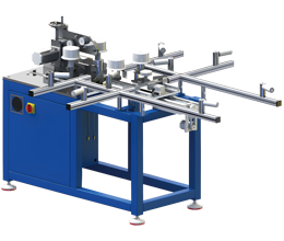
An automatic winding unit produces spiral wound elements.
A six-axis collaborative robot removes the winding element and places it on the press platform.
The platform measures the outside diameter and determines whether the element is acceptable.
Accepted elements continue to assembly, while dimensionally rejected elements are sorted out by the robot.
A handling mechanism places the accepted winding element into the assembly mold.
A second handling mechanism loads a prepared guide ring into the mold.
The press flattens and assembles the guide ring around the winding element.
A third handling mechanism transfers the completed gasket to a collection bar.
This sequence distinguishes the MSWG-25 from a standalone spiral wound gasket machine. A winding machine focuses primarily on producing the sealing element. The MSWG-25 extends the process through dimensional verification and guide ring assembly, creating a more complete finished-product flow.
The product page lists a working range from 1/2 inch to 8 inches and identifies carbon steel and stainless steel as suitable guide ring materials. It also states that the system works well with inner-ring-type gaskets. These specifications describe the published configuration, but buyers should still confirm their exact gasket standard, pressure class, construction, strip width, filler material and ring geometry with SZMATE before final machine selection.
The MSWG-25 production cycle converts a programmed winding recipe into a dimensionally checked and guide-ring-assembled spiral wound gasket.
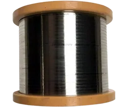
The cycle begins at the automatic winder. Metal strip and filler material are fed into the winding process according to the selected product recipe. The metal strip is formed and wound together with the filler to create the layered sealing element. The start and finishing welds secure the structure.
Winding quality depends on stable strip forming, material alignment, filler continuity and tension. Automatic feeding and programmed motion improve repeatability, but incoming strip thickness, filler width, material condition and tooling wear still influence the result. The line should therefore be supplied with qualified, consistent materials.
The automatic winder determines the base cycle of the connected system because downstream equipment cannot assemble a new gasket until another winding element is available. For the published three-inch example, the specification lists a cycle time of approximately 25 seconds. That number should be treated as a model-specific example under defined conditions, not as a universal cycle for every diameter and construction.
After the winding element is complete, the six-axis collaborative robot removes it from the winder. This transfer replaces repeated manual pickup and placement between independent machines. The robot follows a programmed path and places the element on the inspection platform associated with the press.
The gripper, pickup point and motion path must match the gasket size and physical condition. Buyers should ask how the robot handles the smallest and largest products in the required range, what happens if an element is not seated correctly and how the system detects a failed pickup.
The platform measures the outside diameter of the winding element before assembly. This creates an in-line quality gate between winding and guide ring installation. If the dimension meets the programmed acceptance condition, the element proceeds. If it does not, the robot moves it away from the normal production path.
This step is important because an incorrect winding diameter can cause assembly difficulty or an unsuitable fit with the guide ring. Detecting the problem before pressing prevents a nonconforming winding element from consuming a qualified ring and additional assembly time.
Automatic inspection should still be supported by calibration and verification. The buyer should confirm the measurement principle, resolution, repeatability, calibration method and acceptable environmental conditions. A digital decision is only reliable when the measuring system is stable and the acceptance limits match the approved product drawing.
While the winding element is being handled, the guide ring feeding system prepares rings for assembly. The published system includes two storage positions. One storage supplies rings while the other can be reloaded, allowing replenishment without stopping the entire line under normal conditions.
The listed guide ring loading capacity is 350 pieces. Actual replenishment frequency depends on product size, ring thickness, storage arrangement and production rate. A large nominal capacity is useful only when rings are consistently shaped, separated and presented to the pickup mechanism.
Prepared guide rings must meet diameter, flatness, groove and surface requirements before entering the feeder. An automatic line cannot compensate for rings that stick together, vary in shape or arrive with distorted edges. Upstream ring production and inspection are therefore essential parts of the complete manufacturing system, even though they occur outside the MSWG-25 cell.
An accepted winding element and a prepared guide ring are placed into the assembly mold. The press head then descends and applies controlled force to flatten or deform the guide ring as required for assembly.
The published maximum pressure is 5 tons, generated by a pressurized oil-air cylinder. The necessary pressure depends on ring material, thickness, geometry and gasket size. More force is not automatically better. Excessive or poorly controlled pressure can deform components, while insufficient pressure may produce incomplete seating.
The assembly mold is a critical tooling component because it establishes position and supports the parts during pressing. SZMATE describes a quick-change mold intended to keep changeover below ten minutes. Buyers should request a demonstration of a complete product change, including mold replacement, recipe selection, first-piece production and dimensional approval.
After pressing, a handling mechanism removes the completed gasket and transfers it to a collection bar. The system includes four collection bars. When one becomes full, production can switch to another so the operator can remove finished parts without immediately stopping the line.
This arrangement separates machine cycle time from periodic finished-product collection. It also reduces the risk that operators reach into the assembly area during normal production. The collection method should protect gaskets from bending, impact, contamination and mixing between product batches.
Each MSWG-25 unit performs a distinct function, and the line reaches stable output only when all four units operate at compatible rates.
| Main Unit | Primary Function | Key Production Value | Buyer Verification Point |
|---|---|---|---|
| Automatic winder | Forms and winds metal strip with filler into a sealing element | Controls the base production cycle | Size range, gasket construction, material compatibility and verified cycle |
| Six-axis collaborative robot | Transfers winding elements between winding, inspection and assembly positions | Reduces repetitive manual transfer and stabilizes placement | Gripper suitability, pickup detection, safe operating envelope and recovery logic |
| Automatic press | Measures OD, accepts or rejects elements and completes guide ring assembly | Integrates quality judgment and assembly in one station | Measurement capability, mold design, press force and changeover procedure |
| Guide ring feeding system | Stores and presents prepared guide rings for automatic pickup | Supports continuous operation with dual storage | Ring consistency, loading capacity, refill method and jam detection |
The published specifications define the standard MSWG-25 configuration and provide a starting point for application review.
| Specification | Published Value | Procurement Interpretation |
|---|---|---|
| Work mode | Fully automatic | Main operations are connected through PLC-controlled handling |
| Published size range | 1/2 inch to 8 inches | Confirm exact standard, pressure class and gasket construction |
| Example cycle time | Approximately 25 seconds for a 3-inch gasket | Use only as a reference until verified with buyer materials |
| Changeover time | Less than 10 minutes | Confirm whether this includes first-good-piece approval |
| Maximum press force | 5 tons | Verify suitability for the required ring material and geometry |
| Guide ring loading capacity | 350 pieces | Actual capacity may vary with ring size and storage arrangement |
| Guide ring material | Carbon steel / stainless steel | Run trials with the exact grade, thickness and finish |
| Control system | PLC program | Confirm recipe storage, access control and data availability |
| Nominal line footprint | Approximately 5 m × 6 m | Additional space is required for access, materials and finished products |
| Voltage | 380 V | Confirm phase, frequency and local electrical compliance |
| Compressed air | Published as 0.5–0.8 MPa | Confirm required flow, air quality and connection size |
| Listed component power | Approximately 16.7 kW combined | Connected load is not identical to average energy consumption |
| Listed combined net weight | Approximately 2,010 kg | Confirm shipping dimensions, floor loading and installation method |
The combined connected power figure is calculated from the listed auto winder, robot, press and guide ring feeding system ratings. Actual energy use depends on operating load, idle time and cycle conditions. The combined listed weight is also a planning reference rather than a substitute for the final foundation and shipping drawings.
Practical line capacity equals theoretical cycles minus time lost to changeover, replenishment, inspections, alarms, maintenance and rejected products.
At a 25-second example cycle, the theoretical rate is 144 cycles per hour. Over an uninterrupted eight-hour period, that equals 1,152 theoretical cycles. No production line operates for an entire shift without planned or unplanned losses, so this number should never be presented as guaranteed daily output.
| Effective Utilization Assumption | Approximate Good Pieces per 8-Hour Shift | What the Assumption Must Cover |
|---|---|---|
| 70% | About 806 pieces | Changeover, replenishment, minor stops, quality losses and planned checks |
| 80% | About 922 pieces | Stable materials, trained operators and controlled product mix |
| 85% | About 979 pieces | Mature process with high availability and limited variation |
These figures are illustrations based on the published three-inch cycle, not production guarantees. Larger products contain more material and may require longer winding time. Different constructions, weld sequences and ring configurations can also change the cycle.
In-line outside-diameter inspection prevents an incorrect winding element from consuming a qualified guide ring and additional assembly time.
Spiral wound element diameter can vary because of strip thickness, filler compression, tension, tooling condition, weld placement and springback. A programmed number of turns does not alone guarantee that the finished element matches the required outside diameter.
By measuring the element before assembly, the MSWG-25 creates a control point close to the winding process. A dimensional problem can be detected before the part is pressed into a guide ring. This reduces the amount of material and production time attached to one nonconforming element.
The quality benefit depends on measurement system capability. During acceptance, the buyer should compare automatic readings with a calibrated reference method. Repeat the comparison across small, medium and large products. Check whether the measurement remains stable after tooling changes and over a continuous production run.
Dual ring storage and multiple finished-part collection bars allow replenishment and collection without stopping every production cycle.
A common automation problem is that the primary machine runs quickly but stops whenever an operator must refill components or clear finished parts. The MSWG-25 addresses this issue through two guide ring storage positions and four gasket collection bars.
While one ring storage position supplies the line, the second can be prepared for continued production. When the active storage becomes empty, the system can change to the prepared supply according to its control logic. Likewise, the unloading system can move to another collection bar when one bar reaches capacity.
The dual-storage concept works only when guide rings are consistent enough for automatic separation and pickup. Bent, oily, nested or dimensionally inconsistent rings can cause feeder faults. Upstream inspection and controlled storage are therefore part of automatic-line reliability.
Fast changeover requires coordinated replacement of physical tooling, recipe selection, material preparation and first-piece verification.
SZMATE lists a changeover time below ten minutes for the specially designed quick-change mold. Buyers should clarify the exact starting and finishing points of this measurement. A meaningful changeover begins after the last good product of the previous batch and ends when the first conforming product of the next batch is approved.
Physical changeover may include assembly molds, gripping settings, guide ring storage, strip and filler materials and product collection identification. Digital changeover includes the PLC recipe, measurement limits, robot path parameters and production count.
The MSWG-25 reduces inter-process handling, while separate machines provide greater independence and flexibility for low-volume or mixed production.
| Comparison Factor | MSWG-25 Integrated Line | Separate Automatic or Semi-Automatic Machines |
|---|---|---|
| Part transfer | Robot and automated handling | Usually manual carts, trays or operator transfer |
| OD inspection | Integrated before guide ring assembly | May occur at a separate inspection station |
| Reject sorting | Automatic removal from the normal route | Operator or inspector identifies and separates parts |
| Guide ring loading | Automatic feeder with dual storage | Manual loading or separate assembly machine |
| Finished-part unloading | Automatic transfer to multiple collection bars | Manual unloading and storage |
| Product flexibility | Best for stable products within the configured range | Often easier for unusual or low-volume sizes |
| Capital investment | Higher integrated system investment | Can be staged by process |
| Line balancing | Designed as one synchronized cell | Independent machines can run at different schedules |
| Failure impact | A major station fault may stop the connected line | Other independent machines may continue running |
| Best application | Recurring high-volume inner-ring gasket production | Custom, mixed-size, development or staged expansion |
Conversely, separate machines create queues, repeated handling and quality delays when production volume becomes high. An operator may spend more time moving trays and matching winding elements to rings than controlling the process. At that point, an integrated fully automatic gasket manufacturing line can remove a significant amount of non-value-added work.
A standalone winding machine produces the spiral wound element, while the MSWG-25 continues through inspection, guide ring feeding, assembly and unloading.
The distinction matters when comparing quotations. A fully automatic winding machine can automatically feed and cut strip and filler, perform winding and eject the completed element. It is a strong solution when the factory already has suitable inspection and guide ring assembly capacity.
The MSWG-25 adds robotic transfer and connected assembly. This can be valuable when manual handling between winding and assembly is the main bottleneck. It also reduces the risk that accepted and unaccepted winding elements become mixed before ring installation.
The MSWG-25 can run continuously only when upstream guide ring manufacturing supplies accurate rings at the required rate.
The line receives prepared guide rings; it does not replace the complete ring-production process. Rings may require bending, cutting, welding, flattening, grooving or chamfering, weld finishing and inspection before they enter the feeder.
Calculate the effective output of each upstream operation. If the MSWG-25 requires roughly 144 rings per theoretical production hour at the three-inch example cycle, the ring cell must produce and release rings at a comparable sustained rate or maintain an appropriate supermarket inventory.
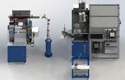
A productive MSWG-25 cell requires more space than its nominal 5 m × 6 m equipment footprint because operators, materials, maintenance and finished products need controlled access.
The layout should include incoming strip and filler staging, guide ring racks, tooling storage, inspection equipment, rejected-part containment and finished-gasket collection. Keep the normal material route separate from maintenance access and electrical cabinets.
Confirm door dimensions and lifting routes before shipment. The listed component weights include approximately 910 kg for the automatic winder, 80 kg for the robot, 740 kg for the press and 280 kg for the guide ring feeding system. The installation plan should define unloading, positioning, floor loading and leveling.
The published electrical ratings total approximately 16.7 kW of connected component power. Confirm three-phase voltage, frequency, protective devices, cable size and grounding with the final electrical drawing. Average consumption will vary, so energy cost calculations should use measured duty-cycle data rather than the sum of nameplate ratings alone.
Compressed air is published at 0.5–0.8 MPa. Buyers should also confirm required flow, dew point, filtration and connection size. Insufficient flow can reduce press performance even when static pressure appears acceptable.
Automation reduces repetitive transfer but still requires operators to replenish materials, verify quality, manage batches and respond to abnormal conditions.
Operators need training in recipe selection, material loading, mold change, alarm response, measurement verification and daily maintenance. Maintenance technicians need control-system backups, electrical drawings, pneumatic diagrams and a critical spare-parts list.
An integrated automatic line requires preventive maintenance across mechanical, robotic, pneumatic, electrical and measuring subsystems.
The line contains more connected devices than a standalone machine, so fault isolation and spare-parts planning are important. A problem at the winder, robot, measurement station, press or feeder can interrupt the complete production route.
Request a recommended spare-parts list divided into consumables, critical spares and long-lead components. Typical categories may include forming tools, cutting tools, welding consumables, sensors, pneumatic seals, relays, drives, robot gripper components and measurement-system parts.
Daily checks should cover material paths, grippers, sensors, guards, air pressure, lubrication points and abnormal noise. Scheduled maintenance should include calibration verification, tooling inspection, filter service and software backup.
A safe automatic gasket line must control winding nip points, welding, robot movement, pressing force, pneumatic energy and maintenance access.
The robot and automatic mechanisms create a defined movement envelope. Even a collaborative robot requires a completed risk assessment for the full application, including the gripper, workpiece, speed, force and interaction with surrounding machines.
The press can apply up to 5 tons, so access to the mold area must be controlled. Guards, interlocks and safe setup procedures should prevent movement while an operator is changing tooling or clearing a fault.
Emergency stops should be accessible from normal operator positions. The line should define a safe restart sequence after interruption so it does not repeat an unexpected motion or press a mispositioned component.
Maintenance procedures should identify electrical, pneumatic and stored mechanical energy. Training must include lockout, jam clearing, robot recovery and handling of sharp metal rings and strips.
The MSWG-25 is best suited to manufacturers with recurring demand for standardized inner-ring spiral wound gaskets within the configured 1/2–8 inch range.
Factories producing repeated standard sizes in medium or large batches.
Manufacturers whose current bottleneck is manual transfer between winding, inspection and guide ring assembly.
Plants seeking automatic OD judgment before ring assembly.
Operations with stable guide ring quality and sufficient upstream ring capacity.
Factories able to support PLC, robotics, pneumatic systems and preventive maintenance.
Manufacturers that can keep the line utilized across one or more shifts.
The line may be less suitable as the only production system for a workshop dominated by very small custom orders, frequent non-standard products or sizes outside the configured range. Such factories may need a hybrid layout combining an integrated line for high-volume products with flexible semi-automatic equipment for specials.
It may also be premature to purchase a full line when the company has not standardized incoming materials, ring dimensions, recipes and inspection. Automation repeats the defined process. If the inputs are unstable, it can repeat instability more quickly.
A complete request for quotation should describe the product mix, required output and factory conditions rather than asking only for the machine price.
Applicable gasket standards and customer specifications.
Minimum and maximum nominal sizes.
Gasket construction, including inner ring and guide ring requirements.
Metal strip grade, width and thickness.
Filler material, width, density and supply format.
Guide ring material, thickness, width, groove and finish.
Annual volume and typical batch quantity for each major size family.
Target good gaskets per shift.
Required dimensional tolerances and inspection records.
Number of changeovers per shift and acceptable setup time.
Available voltage, frequency, compressed air and floor space.
Local machine safety and guarding requirements.
Required language for HMI, manuals and training.
Desired production data, traceability and network connection.
Representative materials for factory acceptance testing.
This information allows SZMATE to verify whether the standard MSWG-25 configuration is suitable or whether tooling, grippers, molds, storage and control logic require adjustment.
A factory acceptance test should demonstrate sustained production, complete changeover, automatic rejection and safe recovery using representative buyer products.
Select at least three products: a recurring high-volume size, a product near the upper configured range and a product requiring a meaningful changeover. Use the buyer’s actual strip, filler and rings whenever possible.
Measure cycle time from an agreed start point to the same point in the next cycle. Confirm whether the figure includes winding, transfer, measurement, ring loading, pressing and unloading. Run enough consecutive cycles to reveal replenishment, feeder and handling issues.
Introduce a controlled out-of-tolerance winding element to verify measurement judgment and reject sorting. Test guide ring depletion, collection-bar switching, material-break detection, emergency stops and restart logic.
Inspect consecutive finished gaskets for outside diameter, assembly fit, ring condition and visible damage. Record machine settings and material batches. Acceptance should also cover documentation, drawings, spare parts, training and software backup.
The MSWG-25 business case should compare total installed cost with annual savings and contribution generated by good finished gaskets.
Total installed cost includes equipment, tooling, freight, duty, electrical work, compressed-air preparation, foundation or leveling, safety modifications, training, commissioning, spare parts and initial material trials.
Annual benefit may include lower manual transfer time, reduced work-in-process, fewer assembly errors, faster dimensional rejection, lower overtime and additional contribution from higher output. Additional theoretical capacity should not be counted as revenue unless customer demand can use it.
Model at least three operating scenarios. The conservative case might use 70% effective utilization, slower ramp-up and more changeovers. The expected case might use 80%. The high-performance case can test 85% after stable materials, trained operators and preventive maintenance are established.
Calculate the cost per good gasket for the current process and proposed line. Include labor, scrap, rework, energy, maintenance and financing. Simple payback is useful, but discounted cash flow provides a better view for a major capital project.
These questions address the most common production, capacity and procurement concerns related to the MSWG-25.
The published work range is 1/2 inch to 8 inches. Buyers should confirm the exact standard, pressure class, winding construction, inner-ring configuration and guide ring geometry because nominal diameter alone does not define machine suitability.
No. Approximately 25 seconds is the published example for a three-inch gasket. Actual cycle time depends on diameter, construction, material, welding sequence, ring handling and configuration. Capacity should be verified with representative buyer products.
No. The line automatically feeds and assembles prepared guide rings. Ring bending, welding, flattening, grooving, chamfering and finishing may require separate upstream equipment before rings enter the feeder.
The press platform measures the winding element outside diameter. Elements that meet the programmed condition continue to assembly, while dimensionally unqualified elements are removed from the normal route by the robotic handling system.
The dual guide ring storage and four collection bars are designed to reduce stoppages during replenishment and finished-part collection. Operators must still reload the standby storage and clear collection bars before all available positions are exhausted.
Send gasket drawings, standards, size range, construction, strip and filler materials, guide ring specifications, annual quantities, batch sizes, target output, tolerances, utilities and floor-space information. Representative materials are also valuable for a production trial.
The MSWG-25 creates value by connecting winding, robotic transfer, dimensional inspection, guide ring feeding, pressing and unloading into one controlled production route.
Its strongest application is recurring inner-ring spiral wound gasket production within the configured size range. The line can reduce manual movement, identify dimensional problems before assembly and support continued operation through dual ring storage and multiple finished-part collection positions.
However, a successful project depends on more than the published 25-second example cycle. Buyers must verify product compatibility, practical capacity, changeover, measurement capability, guide ring quality, upstream supply, maintenance resources and factory utilities.
For a high-volume gasket manufacturer, the correct evaluation is not whether automation looks advanced. It is whether the complete SZMATE line can produce the required mix of conforming finished gaskets at a lower sustainable cost and with better production control than separate machines.
ASME B16.20 – Metallic Gaskets for Pipe Flanges: https://www.asme.org/codes-standards/find-codes-standards/b16-20-metallic-gaskets-pipe-flanges
OSHA 29 CFR 1910.212 – General Requirements for All Machines: https://www.osha.gov/laws-regs/regulations/standardnumber/1910/1910.212
ISO 9001 Explained – Process Approach and Quality Management: https://www.iso.org/home/insights-news/resources/iso-9001-explained.html