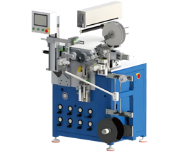
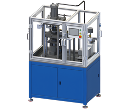
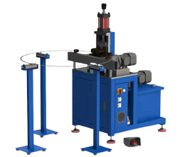
A gasket guide ring may look like a simple metal circle, but producing it consistently requires a controlled sequence of forming, cutting, joining, stress correction, machining and finishing. If one operation is unstable, the ring can become out-of-round, uneven, difficult to assemble or unsuitable for marking and inspection. The result is not only scrap at the ring stage. An inaccurate ring can also slow winding-element assembly and create problems in the finished spiral wound gasket.
For that reason, procurement teams should evaluate ring equipment as a production cell rather than as isolated machines. The correct line depends on ring diameter, strip thickness, flange width, material, batch size, required groove or chamfer, welding method, surface-finish requirement and the relationship between ring output and winding capacity.
This article explains the complete process from raw strip to finished guide ring. It uses published specifications from SZMATE machines to show how equipment can be combined for small, standard and large products. It also includes a capacity-balancing method, quality checkpoints, a comparison table and a practical procurement checklist.
An automatic ring making machine forms straight metal strip into a controlled circular ring and may integrate straightening, servo bending, length control and cutting.
The term can describe one bending unit or a wider line. In the narrow sense, the machine pulls strip through forming rolls and controls the radius until the programmed circumference is reached. It then cuts the strip to length. In the wider sense, a ring-making cell includes welding, flattening, grooving, chamfering, grinding, polishing and assembly preparation.
Buyers searching for a ring making machine should therefore define the finished condition they expect. A cut ring blank is not the same as a welded, stress-relieved, grooved, chamfered and polished guide ring. The quotation must state where the supplier’s process begins and ends.
Guide rings and inner rings are commonly produced from carbon steel or stainless steel strip. The required dimensions and surface treatment depend on the gasket design and standard. Material properties affect springback, weld behavior, flattening force and machining conditions, so the line should be tested with representative production material.
A complete guide-ring production flow typically includes material preparation, bending, cutting, welding, flattening, machining, weld finishing, polishing, inspection and assembly staging.
Receive and inspect strip material.
Straighten and feed the strip.
Bend the strip to the programmed diameter.
Cut the ring blank to length.
Align and weld the joint.
Flatten the ring and reduce distortion or residual stress.
Machine the guide-ring groove or inner-ring chamfer when required.
Remove excess weld height by grinding or milling.
Polish surfaces and edges where required.
Inspect diameter, roundness, width, thickness, groove or chamfer and surface condition.
Mark, store or send the ring to gasket assembly.
Not every product needs every step. Small rings may be produced with a different blanking and forming method. Some rings may require only bending, welding and flattening. Others need groove and chamfer machining before assembly. The process map should identify mandatory operations for each product family.
The line should also show inspection gates. If diameter is verified only after polishing, a bending problem may consume welding, flattening and machining capacity before it is detected. Earlier checks reduce the cost of nonconformance.
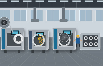
Incoming strip quality sets the physical limits for ring accuracy, weld consistency and surface finish.
Verify material grade, thickness, width, edge condition, flatness and coil identification. Carbon steel and stainless steel can both be suitable, but their springback and welding behavior differ. A program developed for one material should not be assumed to work without adjustment for another.
Thickness variation changes the force required for bending and flattening. Width variation can affect groove position, chamfer geometry and assembly fit. Damaged edges may create burrs or interfere with winding-element placement. Rust, oil or contamination can reduce weld and finish quality.
Create a material lot record that follows the ring through production. At minimum, record supplier, grade, heat or batch identification, width, thickness, received date and inspection status. When rings are produced for critical industrial gaskets, this record supports traceability and faster root-cause analysis.
Store strip in a way that prevents deformation and contamination. The distance from storage to the bending machine should be short and clear. Heavy coils or long strips may require mechanical handling, especially when a large-diameter cell is operating continuously.
Automatic bending converts straight strip into a ring by controlling feed length, forming pressure and radius before cutting the blank.
The SZMATE MRB-08A automatic ring bending machine is a useful reference for large guide and inner rings. Its published work range is 200 to 3,500 mm, with strip thickness from 3 to 5 mm and width from 5 to 30 mm. The machine uses PLC control, servo-driven size control and hydraulic cutting.
The published example cycle is approximately five seconds per piece for an 8-inch ring, with stated accuracy of ±0.3 mm. That number should be verified using the buyer’s material and complete operating definition. Larger diameters contain more length and may require different handling, so one example cannot represent the full range.
The bending program controls how quickly the strip enters the rolls and how much forming force is applied. Springback compensation may be needed. The operator should verify the first ring after any change in material grade, thickness, width or diameter.
Automatic cutting improves length consistency and material utilization. The cut ends must still be suitable for alignment and welding. Poor cut geometry can create a gap, overlap or angular mismatch that later requires excessive grinding.
Welding closes the ring and must control alignment, penetration, excess height and heat distortion.
Before welding, the ends should be aligned so the ring does not develop a step across the joint. Fixtures can hold diameter and edge position. The weld method must suit the material and thickness. In many gasket-ring cells, argon arc welding is used for a clean, controllable joint.
Heat input affects distortion. Excessive heat can pull the ring out of round or create a high weld bead that requires additional finishing. Insufficient heat can create weak fusion. A qualified process should define current, travel, shielding gas, joint preparation and acceptance criteria.
Automation can improve repeatability, but visual and dimensional inspection remains necessary. The joint should be checked for cracks, incomplete fusion, undercut, excessive reinforcement and misalignment. Depending on the product and customer requirement, additional testing may be specified.
Welding is often a hidden bottleneck. A bending machine may create blanks faster than the welding station can close them. Measure actual weld handling time, including loading, alignment, welding, cooling and transfer. If the queue grows, the factory may need multiple fixtures, an automatic welding station or a different work sequence.
Flattening corrects deformation after bending and welding and helps reduce residual stress before precision machining or assembly.
A newly welded ring may not lie flat. Local heat and forming forces can produce waviness, twist or uneven contact. If the ring enters grooving or chamfering in this condition, the machined geometry may vary around the circumference.
The SZMATE MRF-24 ring flatten machine is designed for guide and inner rings. Published information describes a diameter range of approximately 200 to 3,000 mm, workpiece thickness from 2 to 5 mm and width from 5 to 50 mm. Hydraulic operation provides controlled force while the ring passes through the flattening process.
Flattening should not be treated as an uncontrolled attempt to force the ring into shape. Define entry condition, machine setting, number of passes and acceptance method. Excessive correction can change diameter or create new distortion. The operator should verify both flatness and roundness after the process.
Positioning this step before machining protects the accuracy of later operations. It also reduces the chance that a ring will rock or move in a grooving fixture. For high-volume production, the flattening station should be balanced with bending and welding so work-in-process does not accumulate.
Grooving creates the guide-ring locating profile, while chamfering forms the edge geometry required for inner-ring fit and gasket assembly.
Although the operations may be combined in one machine, they serve different functions. A guide-ring groove provides a controlled location for the winding element. An inner-ring chamfer modifies the edge so the components can fit and assemble correctly. The cutter, clamping method and feed path must match the operation.
SZMATE offers equipment for different size ranges. The MGB-22A automatic groove and chamfer machine is designed for smaller products and has a published machining range from 0.5 to 6 inches. The machine can load about 150 rings, and published product information states that one operator may supervise several units under suitable conditions.
For large rings, the MGB-12 grooving and chamfering machine is intended for sizes from approximately 8 inches to 3.5 meters. This division shows why a complete factory may need separate small-size and large-size machining cells.
Inspection should verify groove position, depth, width, concentricity and surface finish, as well as chamfer angle or profile. Tool wear can create gradual drift, so scheduled checks and tool-life records are important. A standard CNC insert may simplify replacement, but the validated cutting parameters should be controlled.
Weld grinding removes excess joint material so the ring surface and edges meet dimensional and assembly requirements.
A high weld bead can interfere with guide-ring assembly, marking, packaging or customer inspection. Manual grinding may create inconsistent local thickness or scratch adjacent surfaces. A dedicated machine controls clamping, cutter movement and material removal.
The SZMATE MWG-15 ring grinding machine is designed for guide-ring and inner-ring weld finishing. Its published range begins at 3 inches, with 2-to-5-mm thickness and maximum width of 60 mm. The listed cycle time is approximately 15 to 20 seconds per side, with semi-automatic PLC-controlled operation.
The process may address the upper surface, lower surface, outside diameter and inside diameter around the joint. Because two sides or multiple areas can be involved, the buyer should confirm whether the quoted cycle includes the complete ring or one processing step.
Grinding quality should be checked with both visual and dimensional criteria. The objective is not merely to make the weld look smooth. The finished area must remain within thickness limits and should not contain sharp transitions that become stress or assembly points.
Ring polishing removes minor burrs and surface marks and creates a more uniform finish before inspection, marking or assembly.
Polishing is different from weld grinding. Grinding removes controlled excess material at the joint. Polishing improves the broader surface condition. A ring may need both processes, one process or neither, depending on the customer and product requirement.
The SZMATE MRP-14 ring polish machine is intended for guide and inner rings of 6 inches and above. Published specifications list 2-to-5-mm thickness, 5-to-50-mm flange width and a cycle time below 20 seconds, with manual loading and optional or integrated dust collection according to configuration.
Dust control is important because polishing creates airborne particles and deposits. Extraction should be sized and maintained for the material and wheel. Operators need appropriate guarding and personal protection according to local requirements.
Define the required finish. Over-polishing wastes time, consumes wheels and can change dimensions. Under-polishing leaves burrs or scratches. A visual standard with accepted and rejected examples improves consistency.
Small-ring and large-ring cells require different loading, clamping, machining and material-flow strategies.
| Production Factor | Small / Standard Ring Cell | Large Ring Cell | Planning Note |
|---|---|---|---|
| Typical bending approach | Compact automatic feed and forming | Servo bending with wide diameter range | Verify material springback by size |
| Ring handling | Manual trays or automatic magazines | Racks, tables or lifting assistance | Prevent deformation during transfer |
| Grooving / chamfering | Automatic loading possible | Manual loading on larger fixtures | Separate machines may be required |
| Inspection | Fast gauges and sampling | Multiple-point diameter and flatness checks | Use one documented method |
| Floor space | Compact multi-machine cell | Wider controlled handling area | Include maintenance and racks |
| Best automation target | Loading, machining and assembly | Bending, cutting and controlled finishing | Automation follows geometry |
A small-ring cell can use magazines and automatic loading because parts are easier to orient and transfer. Large rings need stable support and safe access. The economics of robotics change as part size and product variety increase.
Factories serving both ranges should avoid placing every operation in one congested area. Separate cells can share inspection, marking or material records while using handling equipment suited to each geometry.
Ring-line capacity is limited by the slowest effective operation after accounting for changeover, handling and yield.
Suppose bending creates one ring every five seconds for a representative product, while complete weld handling requires 25 seconds and polishing requires 18 seconds. One welding station becomes the primary constraint. Adding a second bending machine would not increase output. The first investment should address welding capacity or process design.
Create a routing table for each ring family. List cycle time, changeover, number of stations, availability and yield at every operation. Convert each step to good rings per hour. The lowest value is the bottleneck.
Batch transfer can hide imbalance. A large pile of bent blanks may make the bending machine appear productive, while delivery remains limited by machining or inspection. Use work-in-process limits and visible queues to control the flow.
Downstream demand also matters. If the spiral wound line needs 120 guide rings per hour, the ring cell should supply that rate with a buffer for changeover and rejects. Producing far above demand creates inventory and handling risk. Producing below demand starves the assembly process.
A ring quality plan should verify material identity, diameter, roundness, flatness, joint condition, machined geometry and surface finish at defined stages.
Incoming: material grade, batch, width, thickness, edge and surface condition.
After bending: diameter, end alignment and cut condition.
After welding: joint position, fusion, bead height and distortion.
After flattening: flatness, roundness and diameter.
After machining: groove or chamfer geometry and concentricity.
After grinding/polishing: local thickness, burrs, scratches and finish.
Final release: product code, quantity, material lot and inspection status.
Use calibrated gauges and a consistent method. Large rings may require measurements at several angular positions. The inspection plan should distinguish diameter variation from ovality and flatness.
Record tool changes and machine settings when defects occur. This allows the team to identify whether the cause is material, welding, tool wear, setup or handling. Without process records, different causes can produce similar final symptoms.
For recurring high-volume products, process capability analysis can show whether the line is centered and stable. Capability should be calculated using a controlled process and meaningful tolerance, not a small sample selected after adjustment.
A safe ring cell controls pinch points, rotating rolls, hydraulic cutting, welding arc, hot metal, grinding dust, polishing wheels and large-part handling.
Bending rolls and feed mechanisms create in-running nip points. Cutting introduces stored hydraulic energy and sharp edges. Welding requires shielding and fume control. Grinding and polishing require guards, extraction and controlled wheel condition.
Large rings can be awkward even when they are not extremely heavy. Their diameter increases reach and collision risk. Racks should support rings without bending, and aisles should allow transfer without striking equipment or people.
Emergency stops, interlocks and access doors should be positioned according to the actual operator route. Maintenance tasks require lockout points for electrical, pneumatic and hydraulic energy. Jam clearing should never depend on reaching into an energized forming or cutting zone.
Training must include abnormal conditions. Operators should know how to respond to strip misfeed, incomplete cut, weld interruption, tool breakage and extraction failure. A production target should never encourage bypassing guards or inspection.
An integrated ring cell should move material in one direction from raw strip to inspected finished rings with minimal backtracking.
A practical sequence is strip staging, bending and cutting, welding, flattening, machining, grinding or polishing, inspection and finished-ring storage. Place high-interaction stations close enough for efficient transfer but leave service clearance and safe separation between welding and finishing areas.
Welding fumes and polishing dust should not contaminate clean inspection or finished-part storage. Extraction zones may need physical separation. Electrical cabinets and hydraulic units require maintenance access.
Use FIFO locations between major steps. Each batch container or rack should display product code, material lot, quantity and process status. This prevents unprocessed rings from being mixed with accepted parts.
For mixed sizes, store tooling and gauges by product family. Quick-change fixtures are only effective when the correct tools are identified, available and maintained. Visual control reduces searching and setup error.
Ring-cell ROI improves when investment targets the actual bottleneck and reduces the most expensive combination of labor, scrap and delayed output.
Begin with a current-state time study. Measure labor and queue time from strip issue to accepted ring. Identify the operation that limits daily output or creates the largest defect cost. Do not automate a fast, stable process while leaving the true bottleneck unchanged.
Calculate installed cost for each proposed station, including tooling, extraction, utilities, guarding, freight, commissioning and spare parts. Annual benefit may include higher throughput, lower material waste, reduced manual grinding, improved dimensional consistency, lower overtime and fewer assembly problems.
Investment can be staged. A plant may first install automatic bending and cutting, then add controlled flattening and machining, followed by automated loading for high-volume small rings. Large-ring finishing can remain semi-automatic if volume does not justify a dedicated automated station.
SZMATE can support this modular strategy with bending, grooving, chamfering, flattening, grinding, polishing and assembly equipment. The correct sequence depends on the buyer’s products, not on purchasing every available machine at once.
A ring equipment request should define the complete product range, process boundary and measurable acceptance conditions.
Ring type: guide ring, inner ring or other metal ring.
Applicable gasket standard and pressure classes.
Minimum and maximum diameter.
Strip material, grade, thickness and width.
Annual quantity and typical batch size by diameter family.
Required bending accuracy, roundness and flatness.
Weld method and joint acceptance criteria.
Groove dimensions or chamfer requirements.
Required grinding and polishing finish.
Manual, semi-automatic or automatic loading preference.
Target good rings per shift.
Available voltage, compressed air, extraction and floor space.
Required guarding, training, manuals and drawings.
Representative products for factory acceptance testing.
Critical spares and local technical-support expectations.
Ask the supplier to mark each operation as included, optional or excluded. This prevents confusion when a quotation for an “automatic ring line” covers bending but not welding, machining or finishing.
These FAQs address the most common technical and purchasing questions about guide-ring production.
No. A bending machine normally forms and cuts the ring blank. A complete line may also include welding, flattening, grooving, chamfering, grinding, polishing, inspection and assembly preparation. Buyers should define the required finished condition.
Bending and welding can introduce waviness, twist and residual stress. Flattening improves the condition of the ring before machining or assembly. The process must be controlled so it does not create new diameter or roundness errors.
Grinding removes controlled excess material, especially around a weld joint. Polishing improves broader surface condition and removes minor burrs or scratches. Some products need both; others need only one process.
Usually not efficiently. Small and standard rings can use compact automatic loading, while large rings require different clamping and access. SZMATE offers separate equipment concepts for small sizes and rings extending to large diameters.
Calculate good rings per hour for every operation after changeover, downtime and yield. The lowest effective rate is the bottleneck. Compare that rate with winding and assembly demand so the line neither starves downstream equipment nor creates excessive inventory.
Provide ring drawings, diameter range, material, thickness, width, annual volume, batch size, required groove or chamfer, weld and finish criteria, target output and factory utilities. SZMATE can then propose a single machine, modular cell or integrated production flow.
An effective ring production cell transforms strip into an accurate, flat, machined and finished component through a balanced sequence rather than one isolated forming operation.
Begin with material control and automatic bending. Add welding, flattening, groove or chamfer machining, grinding and polishing according to the product family. Inspect at intermediate stages so defects are found before they consume additional processing time.
Use small-size automation where loading and handling can be standardized. Use large-ring equipment and wider work areas where geometry requires stable support. Balance every station against winding and assembly demand. With a process map and representative production data, SZMATE can help configure the required ring-making cell without over-automating low-volume work or under-sizing the true bottleneck.
ASME B16.20 – Metallic Gaskets for Pipe Flanges: https://www.asme.org/codes-standards/find-codes-standards/b16-20-metallic-gaskets-pipe-flanges
OSHA 29 CFR 1910.212 – General Requirements for All Machines: https://www.osha.gov/laws-regs/regulations/standardnumber/1910/1910.212
Nickel Institute – Stainless Steel and the Role of Nickel: https://nickelinstitute.org/en/nickel-applications/stainless-steel/