Marking a gasket is not merely a branding step. In an industrial sealing factory, the mark can connect the physical part to its drawing, material batch, production record and inspection status. That connection becomes especially important when similar-looking gaskets differ in alloy, filler, pressure class or customer specification. A durable identification method reduces the chance that the wrong part reaches assembly, packaging or shipment.
Laser systems are well suited to this role because they can create permanent text, numbers, vector graphics and machine-readable codes without applying ink or a label to the surface. The equipment must still be selected carefully. A flat guide ring, a curved cylindrical component and a high-volume automatic line present different handling problems even if the same information is being marked.
This guide focuses on the traceability use case rather than generic laser technology. It explains what data should be marked, where the information should come from, how marking quality can be verified and how SZMATE’s MLM-0420A, MLM-0420B and MLM-0430F configurations differ. The goal is to help gasket manufacturers connect marking to quality control instead of treating it as an isolated finishing process.
Laser marking equipment is a non-contact identification system that uses a controlled laser beam to create permanent characters, codes or graphics on gasket rings, metal components and related production parts.
For industrial gasket production, the equipment typically includes a laser source, scanning optics, workholding or loading devices, a control computer and software for editing and storing marking content. The surface is modified locally, allowing the factory to identify a part without adding an adhesive label that may detach during handling.
The key production question is not simply whether a laser can mark stainless steel. It is whether the complete system can present the gasket consistently, place the mark in the correct zone, call the right data, verify the result and move the part onward without creating a bottleneck.
On a low-volume workstation, the operator may load a ring and select the approved file manually. On a higher-volume line, part loading, recipe selection and unloading can be automated. The marking technology is similar, but the production control requirements are very different.
Laser marking equipment improves traceability by placing durable identification directly on the physical gasket so production and inspection records can be linked to the correct part.
Many industrial gaskets have similar geometry. A stainless steel guide ring made for one customer can look nearly identical to a ring made for another, even when the material grade, size or specification differs. Visual identification alone becomes less reliable as the number of SKUs increases.
A controlled mark can identify a part number, nominal size, pressure class, alloy, filler code, production batch or customer reference. When a serial number or Data Matrix code is used, the physical mark can act as a key to a larger digital record without placing every piece of information on the gasket.
Traceability is strongest when the marking data comes from the same approved source used by production. If an operator retypes the material grade into the marking software, a permanent laser mark can permanently record a typing error. Integration should therefore reduce manual transcription where the production volume and quality requirement justify it.
Manufacturers exploring this process can review SZMATE’s laser marking equipment category, which includes flat-surface, flat-and-cylindrical and fully automatic configurations for different production needs.
The marking content should identify the gasket clearly while remaining readable, auditable and limited to data that the factory can control accurately.
A practical marking specification begins with the drawing and customer requirements. Common fields may include manufacturer or brand, part number, nominal pipe size, pressure class, material code, filler code, batch or heat reference, production date and inspection status. Not every gasket needs every field.
There are two useful information layers. The first is human-readable data: text that an inspector or installer can understand without a scanner. The second is machine-readable data such as a barcode, QR code or Data Matrix that can point to a more complete database record. Using both can provide fast visual identification and detailed digital traceability.
Do not put unstable business data into the mark unless there is a controlled reason. A long customer description may change or create crowding. A short controlled product code linked to a database is often safer. The mark should remain legible after normal handling and packaging.
Marking location matters as much as content. The approved zone should not interfere with the sealing surface, critical geometry or downstream forming. On guide rings, marking is normally planned on an accessible metal area rather than the active sealing element.
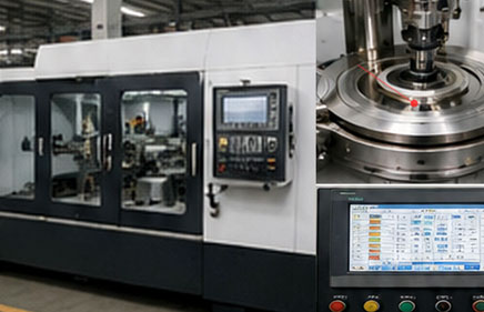
Surface geometry determines how the part must be positioned because a flat ring face and a cylindrical surface require different focus and rotation control.
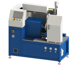
SZMATE’s MLM-0420A is designed for flat-surface marking. Its current specification lists a 1064 nm laser, a standard 110 × 110 mm marking field with a 150 × 150 mm optional field, minimum line width of 0.01 mm and repeatability of 0.001 mm. The product page lists a marking speed of 800 mm/s for the stated single-line example.
MLM-0420B extends the application to both flat and cylindrical surfaces. Its core published laser parameters are similar, but the system adds the ability to control a part that needs rotational marking. This is useful when the identification zone is on a curved component or when text must follow a cylindrical surface.
Workholding is critical for both machines. If the gasket is placed at a different height or angle from one cycle to the next, focus and mark position can change. Fixtures should locate the part from stable geometric features rather than from a rough outer edge when accuracy is important.
The factory should approve a marking envelope for each product family: surface type, allowable position, text height, code size and orientation. Once those variables are controlled, stored files can make repeat production much faster and less dependent on operator judgment.
Manual or semi-manual laser marking equipment provides flexibility for mixed orders, while fully automatic equipment is designed to reduce loading time and maintain a repeatable high-volume cycle.
MLM-0420A and MLM-0420B are appropriate when an operator can load the part and the production mix changes often. They provide a compact marking station and allow the factory to manage many different products without building a dedicated feeding system for every geometry.
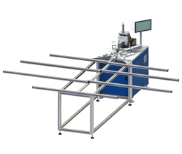
MLM-0430F is configured for fully automatic marking. SZMATE states that it has two loading stations, each supporting about 350 pieces in the described configuration, and can switch supply positions when one is exhausted. The published single-piece cycle is 10 seconds. The laser source is listed at 30 W and 1064 nm.
| Selection Factor | MLM-0420A | MLM-0420B | MLM-0430F |
|---|---|---|---|
| Primary surface | Flat | Flat and cylindrical | Automated gasket/ring marking |
| Laser power | ≤20 W | ≤20 W | 30 W |
| Wavelength | 1064 nm | 1064 nm | 1064 nm |
| Standard marking field | 110 × 110 mm | 110 × 110 mm | 110 × 110 mm listed in current specification |
| Optional field | 150 × 150 mm | 150 × 150 mm | 150 × 150 mm |
| Published repeatability | 0.001 mm | 0.001 mm | 0.001 mm |
| Loading concept | Operator-loaded workstation | Operator-loaded with cylindrical capability | Dual-station automatic loading |
| Published cycle reference | Application-dependent marking speed | Application-dependent marking speed | 10 seconds per piece |
The correct selection depends on volume and product stability. An automatic feeder creates value when the same ring family runs repeatedly. If the factory changes diameter, fixture and data every few pieces, a flexible manual station may produce better overall utilization.
Mark verification should confirm content, position, readability and permanence rather than judging the result only by whether the text is visible.
The first check is data accuracy. Compare the marked part number, material and batch with the production traveler or electronic record. This catches data-selection errors before the batch continues. If machine-readable codes are used, scan them with the same type of reader used downstream.
The second check is geometric. Confirm that the mark sits within the approved zone and does not cross an edge, groove or critical surface. Text height and code size should be defined so the information remains readable after normal handling.
The third check is contrast and completeness. A laser parameter set that works well on one stainless steel finish may look weak on another. Power, frequency, speed and focus interact. The approved recipe should be qualified on representative material, not developed on a polished sample that differs from production parts.
Where traceability is important, retain an inspection record for the first piece after each changeover. A simple camera system or code reader can automate verification in high-volume cells, but even a manual check is effective when the acceptance criteria are clear.
Laser marking creates the most value when the physical code is linked to material, machine and inspection records already used by the gasket factory.
A serial or batch code can connect a finished gasket to the stainless steel heat, graphite lot, machine recipe, operator, inspection result and production date. The mark does not need to display all of that information. It needs to provide a reliable key to retrieve it.
For higher-volume production, the marking program can receive data from a manufacturing execution system or production database. The system should validate that the correct product recipe is active before a part is marked. A duplicate serial-number check can prevent two gaskets from receiving the same identity.
Traceability is particularly useful for industrial gaskets supplied to petrochemical and energy applications, where buyers often need clear material and production documentation. The specific record requirement comes from the contract and applicable standard, but a durable mark simplifies physical-to-digital matching.
A good system also records rejects. If a code is unreadable or the wrong program was selected, the part should be contained and the serial status changed rather than simply re-marked without a record. Traceability loses value if corrections create duplicate or ambiguous identities.
Marking capacity depends on loading, data exchange, actual laser time, verification and unloading, not on beam speed alone.
The MLM-0430F published 10-second cycle provides a simple example. The theoretical ceiling at one part every 10 seconds is 360 parts per hour. Across an uninterrupted eight-hour shift, the theoretical total is 2,880 parts. Real production will be lower because loading-station replenishment, changeovers, inspections, alarms and rejected marks consume time.
| Effective Utilization | Illustrative Output from a 10-Second Cycle | Interpretation |
|---|---|---|
| 70% | About 2,016 pieces per 8-hour shift | Conservative planning with normal stops and product changes. |
| 80% | About 2,304 pieces per 8-hour shift | Stable product family and trained operation. |
| 85% | About 2,448 pieces per 8-hour shift | Mature process with high availability. |
These figures are planning examples, not guaranteed SZMATE output. Actual cycle depends on mark complexity, code size, part handling and configuration. A large Data Matrix plus multiple text fields may take longer than a short part number.
For manual stations, calculate operator touch time. If the laser completes the mark in two seconds but the operator spends eight seconds loading, checking and unloading, automation should target the handling process rather than trying to increase beam speed.
Laser marking equipment requires controlled beam enclosure, safe access, fume management and preventive maintenance appropriate to the installed laser class and application.
Industrial fiber lasers can present eye and skin hazards if the beam path is not properly contained. The complete machine should use guarding and interlocks appropriate to the system design. Operators should not rely on normal eyewear as a substitute for engineered enclosure and safe procedures.
Marking can also generate smoke or particles as the laser interacts with coatings, oil, plastics or surface contamination. Extraction should be matched to the material being marked. A clean metal surface produces a different fume load from painted or coated parts.
Optical components, fixtures and sensors need regular inspection. Dust on a protective window can reduce marking quality and eventually damage components. Fixtures should be checked for wear because location error can appear as a laser problem when the true cause is mechanical positioning.
SZMATE lists laser-source life up to 100,000 working hours for the MLM-0420A, MLM-0420B and automatic system descriptions. Source life does not eliminate maintenance of fans, extraction, motion components, protective optics or electrical systems. A spare-parts plan should cover the complete workstation.
A laser marking RFQ should describe part geometry, material, content, production rate and verification requirements so the supplier can design the correct optics, fixture and loading method.
Send representative gasket drawings and photographs. Identify the exact surface to be marked and whether it is flat or cylindrical. State the smallest and largest part, material grades and surface finish. Provide the expected text height, number of characters, barcode or Data Matrix requirement and allowable mark area.
Define the data source. Will the operator select a stored file, scan a job traveler or receive information automatically from a database? If serial numbers are required, explain the numbering logic and whether the machine must confirm uniqueness.
State the target output as accepted marked parts per hour, not only laser scanning speed. Include batch size and changeover frequency. The supplier can then determine whether an operator-loaded system or automatic feeder is more appropriate.
Finally, connect marking to the wider gasket machine process. If the station will be installed after ring production or final gasket assembly, provide upstream cycle time and downstream packaging requirements. A marking machine that is twice as fast as the rest of the line may not need expensive automation, while a slow manual station can become a major bottleneck on a fully automatic cell.
Data control is as important as optical quality because a perfectly readable mark is still a defect when it contains the wrong part number, material or batch code.
The safest workflow reduces manual typing. Product codes and customer fields should come from an approved job record whenever practical. If an operator selects a stored marking file, the file name should match the product code used on the traveler, and access to edit master templates should be limited. For serial marking, the system should record the last issued number and block unintended duplication.
Changeover is a common error point. The previous batch may still be displayed on the marking computer while the next gasket has already arrived at the station. A first-piece approval should therefore compare the physical gasket, active job, screen data and finished mark before full production starts. Barcode scanning can make this check faster when the factory has suitable digital records.
Rework also needs a defined rule. Simply marking over incorrect information can create an ambiguous part. The quality plan should state whether the gasket may be re-marked in a new approved location, whether the incorrect mark must be removed, or whether the part must be scrapped. The decision should be recorded with the serial or batch history.
For automated cells, use interlocks between part identity and recipe selection where feasible. The goal is not to add unnecessary software complexity. It is to prevent the most expensive marking failure: permanently applying correct-looking information to the wrong gasket.
These FAQs address the most common technical and purchasing questions about gasket traceability and laser marking equipment.
Common fields include manufacturer, part number, nominal size, pressure class, material code, batch or serial number and customer reference. The exact content should follow the drawing, customer specification and applicable standard.
MLM-0420A is intended for flat-surface marking. MLM-0420B can mark both flat and cylindrical surfaces, making it more suitable when the identification area requires controlled rotation or curved-surface positioning.
The fully automatic model is better suited to recurring, higher-volume parts that can be presented consistently through its loading system. Its published reference cycle is 10 seconds per piece, but the actual cycle should be verified with the required mark and gasket geometry.
The mark should be placed on an approved non-sealing area and qualified with suitable laser parameters. Excessive energy, poor focus or the wrong location can affect the surface, so the production recipe and marking zone should be controlled.
Use a compatible code reader after marking and define minimum readability criteria. For high-volume production, a camera or scanner can be integrated into the cell so unreadable codes are contained before packaging.
Provide part drawings, surface geometry, material, marking content, code format, mark area, target output, batch sizes and integration requirements. Also state whether loading should be manual or automatic and whether the machine needs database communication.
Laser marking equipment should connect the finished gasket to controlled production data, not function as a decorative identification step added at the end of manufacturing.
MLM-0420A provides a flexible flat-surface workstation, MLM-0420B extends marking to cylindrical surfaces, and MLM-0430F adds automatic loading for recurring high-volume production. The correct choice depends on geometry, cycle demand and how the factory manages data.
The strongest traceability system defines what must be marked, where the data originates, how the mark is verified and how rejected or reworked parts are controlled. When those rules are clear, SZMATE laser marking equipment can become a practical link between the physical gasket and its material, process and inspection history.